4.4. Copper Area Clear
For details see the Paint Area section in the Geometry Object reference.
Removing large areas of copper is necessary when trying to avoid shorts due to dust, rust, etc, or in RF circuits, where the remaining unused copper is just unwanted parasitics. This tutorial shows how to eliminate all copper that is not specified in the Gerber source, while still being able to selectively choose what to clear.
Open a Gerber file as explained in previous tutorials.
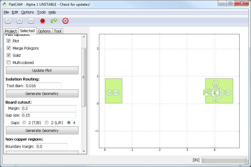
In the Selected tab for the Gerber Object, under Non-copper regions, provide Boundary Margin and click Generate Geometry. This creates a new Geometry Object containing a bounding box around the Gerber object, with the given margin. Then subtracts the Gerber object from the bounding box, resulting in a Geometry object with polygons covering the areas without copper.
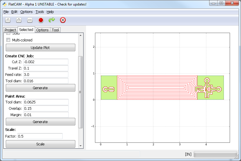
Now we can choose which polygon we want to “paint”, this is, draw a tool path inside it to cover all its surface. In the Selected tab for the newly created Geometry Object, under Paint Area, provide the following:
- Tool diam.: The diameter of the tool that will be used to cut the area.
- Overlap: Fraction of the tool diameter by which to overlap each passing cut. The default value of 0.15 is the minimum to ensure no copper is left in 90 degree turns of the tool path.
- Margin: Distance for the tool to stay away from the polygon boundary. This can be used to ensure that a large tool does not touch copper edges that have or will be cut by a smaller more precise tool.
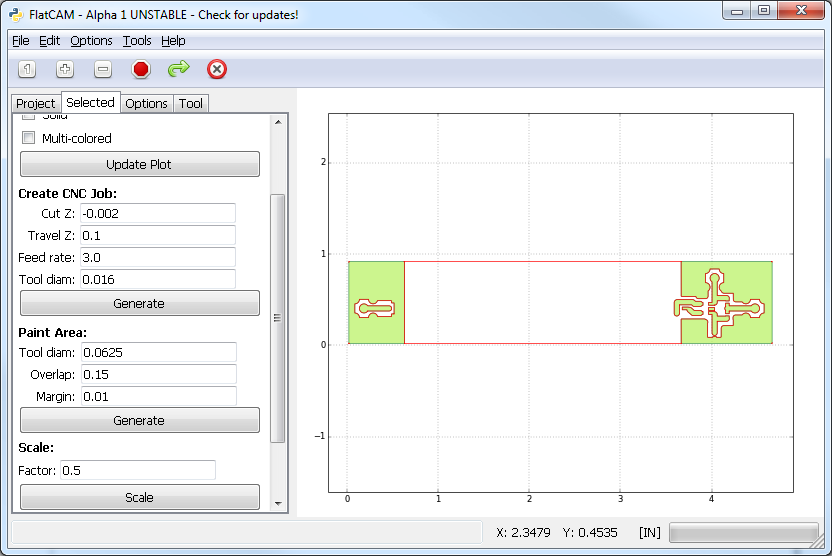
Click on Generate and then click on the plot inside the polygon to be painted. This will create a new Geometry Object with the desired tool paths.