6. Geometry Editor
6.1. Introduction
The Geometry Editor is a drawing CAD that allows you to edit a FlatCAM Geometry Object or create new ones from scratch. This provides the ultimate flexibility by letting you specify precisely and arbitrarily what you want your CNC router to do.
6.2. Creating New Geometry Objects
To create a blank Geometry Object, simply click on the menu item Edit→New Geometry Object or click the New Blank Geometry button on the toolbar. A Geometry object with the name “New Geometry” will be added to your project list.
See also
FlatCAM Shell command new_geometry
6.3. Editing Existing Geometry Objects
To edit a Geometry Object, select it from the project list and click on the menu item Edit→Edit Geometry or on the Edit Geometry toolbar button.
This will make a copy of the selected object in the editor and the editor toolbar buttons will become active.
Changes made to the geometry in the editor will not affect the Geometry Object until the Edit→Update Geometry button or Update Geometry toolbar button is clicked. This replaces the geometry in the currently selected Geometry Object (which can be different from which the editor copied its contents originally) with the geometry in the editor.
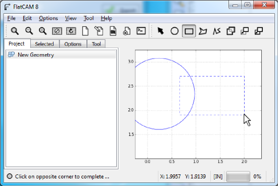
6.3.1. Selecting Shapes
When the Selection Tool is active in the toolbar (Hit Esc), clicking on the
plot will select the nearest shape. If one shape is inside the other,
you might need to move the outer one to get to the inner one. This
behavior might be improved in the future.
Holding the Control key while clicking will add the nearest shape
to the set of selected objects.
6.3.2. Creating Shapes
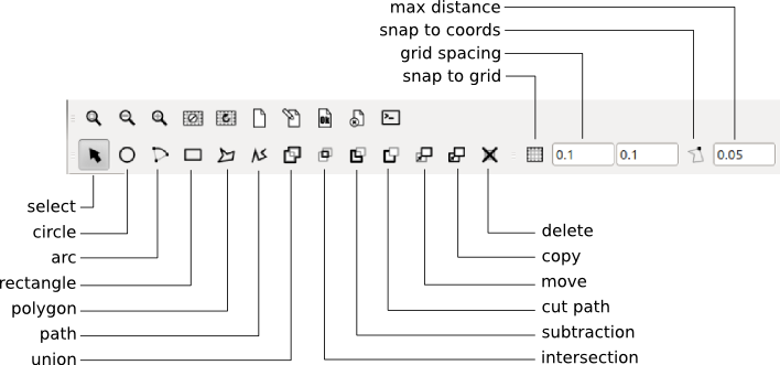
The shape creation tools in the editor are:
- Circle
- Arc
- Rectangle
- Polygon
- Path
After clicking on the respective toolbar button, follow the instructions on the status bar.
Shapes that do not require a fixed number of clicks to complete, like
polygons and paths, are complete by hitting the Space key.
Certain shape tools can have different options or modes. By hitting o and/or p the tool will cycle through its options and/or modes.
See also
The FlatCAM Shell commands add_circle, add_poly and add_rect, create shapes directly on a given Geometry Object.
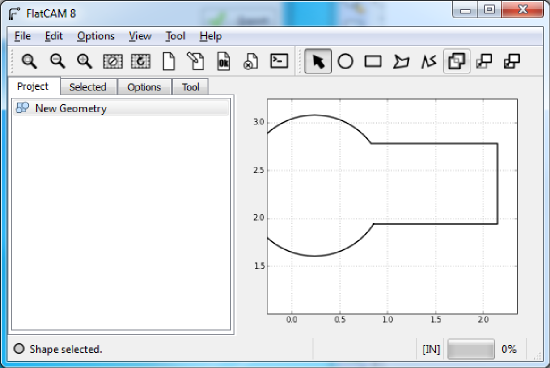
6.3.3. Union
Clicking on the Union tool after selecting two or more shapes will create a union. For closed shapes, their union is a polygon covering the area that all the selected shapes encompassed. Unions of disjoint shapes can still be created and is equivalent to grouping shapes.
See also
The FlatCAM Shell command geo_union executes a union of all geometry in a Geometry object.
6.3.4. Intersection
Clicking on the Intersection tool after selecting two or more shapes will create a new shape from the intersection of the selected shapes. The original shapes are deleted.
6.3.5. Subtraction
Multiple tool shapes can be subtracted from a target shape. Select the target shape first, then tool 1, tool 2, etc. and click on the Subtraction tool button. The original target shape is deleted, and a new geometry consisting of the target minus the tool shapes is created. The tool shapes remain untouched.
6.3.6. Cut Path
Multiple tool shapes can be subtracted from a target shape, which is first converted to the linear paths of it’s boundary. Select the target shape first, then tool 1, tool 2, etc. and click on the Cut Path tool button. If no tool shapes are selected the target is simply converted from a polygon to its linear boundary.
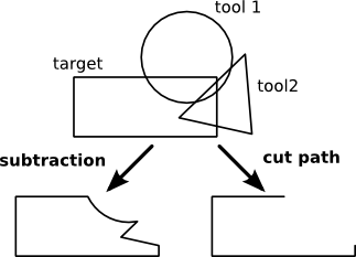
Difference between the Subtraction and Cut Path operations.
6.3.7. Moving and Copying
The Move and Copy tools work on selected objects. As soon as the tool
is selected (On the toolbar or the m and c keys) the reference point
is set at the mouse pointer location. Clicking on the plot sets the target
location and finalizes the operation. An outline of the shapes is shown
while moving the mouse.
See also
The FlatCAM Shell command offset will move (offset) all the geometry in a Geometry Object. This can also be done in the Selected panel for selected FlatCAM object.
6.3.8. Cancelling an operation
Hitting the Esc key cancels whatever tool/operation is active and
selects the Selection Tool.
6.3.9. Deleting selected shapes
Selections are deleted by hitting the - sign key.
6.3.10. Grid and Snap
The coordinates entered by clicks of the mouse can be made to “snap” to certain predefined coordinates. These are the grid coordinates and coordinates in shapes already entered in the editor. Snapping to either of these can be turned on and off separately by clicking on the corresponding buttons on the toolbar.
Snapping to the grid coordinates applies to the whole drawing canvas. Wherever you click, the coordinates given to the program are those of the nearest grid coordinated. The grid coordinates are defined by specifying the grid spacing for the X and Y axes in the corresponding inputs in the toolbar.
Snapping to shape coordinates applies only when the pointer is within a minimum distance of the nearest point in the shape. This minimum distance is specified in the corresponding input in the toolbar. If within this minimum distance, then the coordinates given to the program are those of the nearest point in the shape. If beyond this minimum distance, snapping to shape coordinates is ignored and will snap to the grid if also enabled.
A small dot in the drawing canvas provides a preview of where the pointer would snap.